29 Oct

salepredict2: we are live

I’ve finished the base engine of the Sale Predict project. If you go to SalePredict.com and fill in some of your sales and fails, then it will be able to predict the chance of success for any prospective jobs you have.

For example, let’s say you have successfully sold to 25 companies before, and 25 other companies have turned you down. Let’s say you also have a list of a further 25 companies that you want to approach, but because each of these takes a few hours of research and negotiation, you would prefer to work on them in order of which are most like companies that you have already sold to.

All you need to do is put in the 25 sales and fails, and a neural network will be automatically trained up based on that data, which will then be able to analyse the 25 prospects that you have.

The engine currently accepts logins via LinkedIn and Facebook. I will add more.

You are given 100 free credits as soon as you login. This lets you test it out to see if it works for you. I will add a payment method shortly for increasing the number of available credits. 100 should be enough for anyone to realise how effective this is.

I’m working on an automated test at the moment to figure out exactly how successful the engine actually is. The test works by taking a list of sales and fails, then doing a round of tests on each of those websites, temporarily changing the website to a “prospect” so the system does not know if it was a sale or a fail, then retraining the network on the other domains, and seeing if it accurately predicts the original value (sale or fail) for the test domain. This will take a while to run, so I’ll post the results in the next article.

27 Oct

salepredict1: the Sale Predict project

Around April of this year, I had an idea that I wanted to pursue. I felt it would make an important difference to our business (FieldMotion). The itch was so strong that one weekend, I set up a server and wrote a prototype of the idea in my own time. It worked perfectly. But, it solved a problem that we weren’t interested in anymore, so the work I did on it was mostly wasted. A by-product of it become some useful information, but not the main part of it.

Okay – let’s look at the problem.

Let’s say you’re a business that is trying to expand. You get your work by contacting other businesses that you think may need your product, and trying to get them to work with you. Cold-calling, or trying to arrange a meeting through mutual friends, etc.

The old way to do this would be to get a phone directory, find a list of companies in an industry that you think is right, and just start calling, working each number one by one until you find one that sticks.

But this is usually a waste of time. Either the prospects already have a solution, have no interest, or are too dissimilar to those you’ve sold to before so you can’t establish a common ground.

The problem, shortened, is this: How can you take a long list of potential clients, and order them so that those most likely to buy from you are first in the list?

A solution to this came to me earlier this year. You need to find companies that are similar to those that you have already signed with, but that are not similar to companies you failed to sign with. This is a top-level description, obviously. The technical details of how to measure similarity are beyond this article.

To do this, I wrote a program that takes three lists of domain names:

  1. domain names of companies that you have done business with.
  2. domain names of companies that you cannot do business with (either they’re too unsuitable for your work, or they just said No for any reason).
  3. a long list of domain names of companies that you want to figure out what order in which to call them.

The program reads the front page and all pages linked to the front page of all mentioned domain names, extracts words and “n-grams” (groups of words), and figures out using a neural network what kind of language is used by companies that you usually sell to.

After this, it can then come up with individual numerical scores of how suitable each prospective company is.

I ran this on a list of about 50,000 companies as a test back in April, to see what it would say about my own company’s chances with those prospects. In the top 10, it named a company that we had actually talked to a few years before and that had said they would go with us except we were too young at the time. In the bottom 10, it listed a charity shop, which is totally not our target audience. The thing worked!

But, we don’t work in that way anymore, so it turns out that the list generated by the machine was never used. Oh well.

This week, I’ve decided to revive it and make it generally available. So this weekend, I will work on a simple website to make it possible to generate your own domain lists. It will allow a list of, say, 50 domains free, but anything beyond that will cost. Hosting costs money, and this uses a lot of heavy computation.

26 Oct

dehumidifier 3: hot-plate hiccough

Yesterday, I was hoping to continue work on my dehumidifier project; using a desiccant wheel to adsorb water onto silica gel balls on one side of a machine, and hot air to evaporate water from the balls (regenerate them) on the other side.

The hot-plate arrived for the machine. I tested it, using an old 12V adaptor for power supply. It works well – heats up very quickly. I don’t know what its limits are, but I feel that 105°C is well within its capabilities.

But instead of then working on the machine itself, I spent a few hours making space on my son’s laptop and then installing the Unity development platform. I’ve been trying to get him away from Scratch and onto something more practical, because Scratch is nice, but it’s a dead end.

You won’t find people designing grown-up programs in Scratch, because it simply doesn’t have the capabilities. Database access, complex graphics, file manipulation.

But Unity does, because it binds naturally to some languages that you can then use elsewhere. In this case, C#. But, beggars can’t be choosers!

I bought him a book on how to start coding in C# by creating a game in Unity. With the book, you build a side-scroller game. I really hope he likes it. More than that, I hope the book is not obsolete already!

On the desiccant wheel project, I realised there is a really bad problem – in order to regenerate, the silica gel balls must be baked at more than 100°C in order to let the water evaporate.

PLA (the plastic I print in at the moment) melts at 180°C, but its glass-transition temperate (its Tg) is between 65°C and 70°C. That means that if I have a section of my machine which is around 105°C, then the plastic there may warp.

While this is a real problem, I don’t think it’s insurmountable. The first thing I will do is to just try it as if it will all just work out fine. You never know! And if it turns out there is a problem, I will come up with a solution. That’s what I do.

The biggest warping problem will be the grill on the inner-facing part of the desiccant wheel (green in the image), which keeps the silica gel ball bags from falling out. If that warps, then it will quickly jam the wheel from turning. A redesign of the wheel is major. It would involve changing how the wheel is turned, and probably changing the orientation of the entire machine.

The way I have it at the moment, the wheel rotates on-edge, with two big circles with small air-holes in them, to allow air into the silica gel balls contained inside. If I was to change the orientation so the wheel is held flat with the green grill facing upwards, then the grill would not be needed at all, and the hot air could be blown directly onto the bags themselves.

This is a major change to the design, though, because I would then need to change how to wheel is balanced (currently two ball-bearings on the edge) and how the wheel is rotated in the first place (currently a gearbox held against the grill).

A possible solution is to move the gearbox underneath the flat wheel. Hmm… Yeah, I think that’s actually a good solution. I have a plan now.

22 Oct

new printer progress

What are 3D printers for? Printing new 3D printers! I’ve finished printing the CoreXY parts for my new printer. CoreXY is the method I’m using to control the X and Y axes (left/right, forward/backwards), using parts designed by Louis Zatak who put them on Thingiverse. He also provided parts for Z axis bed lift as well , using the same belt trick that the CoreXY uses.

The dimensions I’m printing are probably much too large – I went for 50cm cubed, which might end up with a print volume of about 44cm cubed, which is 8 times larger than my current printer (an Anet A8).

There will be problems, I’m sure – with 50cm rods, the x-carriage will probably droop near the middle. I have an idea how to solve that if it happens, but we’ll see if it’s necessary!

All that’s left to get for this new printer are some rods for the x-carriage, the y axis, and the z-axis, and a hot-bed. The hot-bed is not strictly necessary, but it will make it work much better. without a hot-bed, prints might curl upwards, and will probably have trouble sticking to the print bed.

After this is finished, I have a plan to build a brief-case sized foldable 3D printer.

The CoreXY design is compact and may be foldable, so I’m going to try find a way to have the z-axis fold upwards towards the CoreXY frame, and then fold the arms of the mechanism inwards. In my head, it works…

21 Oct

straight barrel door bolt

One of my students wanted a straight barrel door bolt printed for his door, because his dog kept on opening it. I designed one up in FreeCad in a few minutes and printed it out with an Anet A8 3D printer during today’s CoderDojo class.

The design is available now on Thingiverse.

The design was deceptively simple. Even though the shape of the thing looks difficult, it’s actually quite easy.

First, we make the base-plate, which I set as 4mm thick for strength. Instead of making three separate pieces, I opted to build it all as one long one. You’ll see what I mean.

Next, I put a cylinder right along it. This will be the outside of the barrel. Notice that I have it overlapping 2mm into the base. The walls of the barrel will be 2mm thick.

And to strengthen the barrel’s connection to the baseplate, I added a cuboid reaching down as a tangent from the cylinder.

I grouped those together using the Union tool.

Next, I worked on the bits that I needed to cut out of the barrel.

First, there’s the cylinder for the bolt. I made sure the leave 2mm in the near end so the bolt didn’t just come right out of the lock when opening it.

Then there’s the channel that the bolt handle slides along.

When locked the bolt handle needs somewhere to slide down into. It needs to be the same width as the channel from the previous step.

Finally, I separated the barrel into three pieces. First, by cutting a 1mm gap to cut off a chunk that connects to the door jamb.

And then a slice that has two uses – first, to let us put the bolt into the barrel in the first place (we’re not printing the bolt inside the barrel, so need a way to put it in). It also acts as a place for the bolt handle to rest when the lock is open. Its width is the same as the earlier two channel cuts.

Lastly, I needed to add 8 cones where the screws should go.

I grouped all of those together then did a cut of that group from the original group I made, which resulted in this:

The bolt itself was next.

First, create a cylinder that is .1mm in radius less than the gap in the barrel and long enough to reach the jamb end from the near end of the main body of the barrel.

Next, add a cylinder for a handle. Its radius should be .1mm smaller than half the width of the channels it slides in.

And then a sphere which serves no real purpose but it looks nice.

Finally group the bolt together into one object, and pull it back in the lock to make sure it fits. If it doesn’t, then adjust whatever you need to!

When we printed this out during class today, the print was difficult to remove from the glass on the hot-bed afterwards. I found it much easier to remove later on when I printed another of them for myself. The difference was that in the class, the hot-bed was still about 60°C, while at home, I was busy with other things and didn’t notice it had finished printing for a while, so it was more like 40°C. So, if you have difficulty removing a part from your 3D printer, maybe just let it cool.

19 Oct

missing layers in prints

I printed out a terrain piece for a friend to use in his Warhammer 40k game. His group was so happy with the print that they told me they would pay for more, so I went looking for more designs that would suit their purpose (technological debris on a sci-fi backdrop).

I found this really nice design of a crashed “killabot” (pictured above) – a robot driven by a race of aliens called Orks.

I priced it at €5.65 – €0.65 for the cost of the filament, and €5 for the time to setup and print it. This is actually quite a ridiculously low number compared to other people that print things professionally (see 3dhubs.com for your local supplier!).

It was going to take about 8 hours to print, according to the slicer program (Cura). I set it to print about 10:30pm.

This morning, I went to check on my 3D printer (an Anet A8), and noticed it was doing something strange at around the 80% mark – some missing layers in a part of the print were leaving obvious bands in the model.

After checking the Layers view of Cura, I saw that what appeared to be a solid model in the default view turns out to have some errors in it that cause Cura to print out some empty layers (pictured below). This is bad, as it can cause later layers to blob.

Cura has a number of built-in mesh fixing algorithms that can be used. It is not always obvious which one (or combination) will fix the problem so you may need to play with it.

In this case, I managed to fix the missing layers by using “Keep disconnected faces”, which is a last resort option. Here’s the fixed view:

I’ve left the faulty print to continue on, because I think the missing layers were few enough that the thing as a whole will still bond together well, but in future, I’ll take a close look of the layers view of a print before I start an 8 hour print…

18 Oct

printing a new printer

I promised myself that the first major thing I would complete with my Anet A8 3D printer was to print another printer.


After calibrating the A8, I found a design online that I liked (the MyCore CoreXY design on Thingiverse (pictured)) and printed out all of the parts needed for both the CoreXY part and for the bed.

I’ve encountered two problems so far:
1. the Y axis rail sliders are designed for LM6UU bearings, but I have LM8UU, so they don’t fit.
2. the MDF I have, which will be used for the walls and floor of the printer, is too thin for the design I printed out

These are easy enough to fix, though.

I can simply adjust the radius of the holes on the Y axis sliders and print them out, fixing the bearing radius issue.

The MDF is slightly harder. I could go out and buy new wood, but I don’t like spending money when there is a free solution in front of me. So, I’m going to thicken up the parts of the MDF box that the plastic parts need to interact with.

If I glue two extra strips of MDF over the existing sheet, that should bring it up to thickness, and should also strengthen the MDF against warping under pressure.


To do this, I needed some G-Clamps for gluing the MDF. I found a wonderful print on Thingiverse which turns out to be very strong when printed at 35% infill. The Anet A8 even did a great job on the knurling detail on the end of the screw (pictured).

I will also need to print out some corner clamps, but there are designs available for that as well.

I love 3D printing! Everything you need, someone has already designed and shared, or you can design for yourself.

After I’ve finished fixing the thickness problems and bearing holes, I need to make a bed for the printer to actually work on. For the first few weeks, it will be an unheated bed, as I haven’t yet ordered a heated bed online. Maybe I could design and build one myself? Or an alternative is to totally enclose the printer and heat the air itself in there to 60 deg – make the thing into a small oven.

Actually, that’s something I’ve been considering anyway – totally enclosing the printer, but having tubes feeding cold air to the fans.

17 Oct

dehumidifier 2: Rolling the drum

I tried setting this up so that the drum could be rolled from an elastic band or cog against the edge of the drum, but it turned out there was a simpler way – the little air-holes in the drum are an equal distance apart, so I designed and printed a gearbox that could turn the drum using those holes.

It sacrifices a little bit of surface area for the cold side of the drum, but I don’t think it will make a huge difference.

I made a few 1mm errors in the gear box prototypes, but when I corrected them, it worked as soon as I applied power to the motor. The motor I’m using in this case is one of the standard yellow geared motors (like this).

I’m still waiting for the heating element to arrive, but have a few fans I can use to get started on the airflow. I don’t even know what size the heating element I ordered is, so can’t design that side yet, but I can design the cold side while I wait. I’ll get started on that tonight.

The 3D printer I’m using is an Anet A8, and I have to say that it’s a dream to work with compared to my old Makibox 3D printer. I was amazed when I printed out the drum and enclosure for this project and they fit perfectly. With the Makibox, the circles would have been flattened and I’d have to sand away any bits that rub, but this one is just perfect.

Even the gearbox would have been impossible to print on the Makibox. The Anet A8 is so good that when some of my students were asking me for a bill of materials to make a 3D printer, I told them that even though it would be possible to spend €120 or so and make a 3D printer from scratch, they’re better off spending $150 and buying one of these ones instead.

10 Oct

dehumidifier 1: Dehumidifier project

I recently finished building the frame of a shed, and covered it with temporary cladding (MDF and plastic) to protect it during the winter until I have more time and money next year to continue with it.

There is a small lake starting to grow in the shed. I don’t think it’s coming up from underneath the soil, and the door end of the shed is covered in plastic to stop rain coming in, so I think the lake is forming from condensation. The air in the shed is basically dumping water on the inner walls of the shed and that water is then rolling down and converging in a large pool.

Because the shed was being built to house a lab, I had planned on building a dehumidifier at some point anyway (I like to build things, even if it might be easy to buy them), but this is encouraging me to get on with it now and build it early.

So over the last week, I bought a half-kilogram (500g) of desiccant crystals, which just arrived, and I’ve started designing the machine.

I’m using the idea of a “desiccant wheel” – a constantly turning wheel where most of it is adsorbing water, and the final part is being dried of its water and regenerated, with the water being blown out as damp air, and either collected in a jar, or dumped outside (what I’ll be doing).

I designed a small wheel last night and started it printing. It’s 60mm in radius (12cm diameter), so really small for this purpose, but as this is my first time making a dehumidifier, I want to make something small and test it, before making a bigger one.

You can see from the image that the wheel is segmented into six parts. The idea is that the wheel will revolve about once an hour, with each segment getting about ten minutes of that hour with hot air being blown through it while cold air is blowing through the rest.

Heat encourages desiccant crystals to dry, with the collected water evaporating and making the hot air damp. That hot air will be blown into a tube that leads outside the shed. Eventually, I may use the water for an indoor gardening setup, but for now, I’ll just get rid of it.

The 5 remaining segments will have cold air blowing through them, with the dampness in that air being adsorbed onto the surface of the crystals, getting those crystals ready for their next ten minute session in the hot air drying part.

I’m waiting now for the heating element to arrive so I can design the fan section and the electronics to keep the temperature constant.

When the hardware is finished, I’ll then need to start testing it with different temperatures, different fan speeds, different wheel speeds, to see how to get the most moisture out as quickly as possible.

I’ll put my design up on Thingiverse as soon as I’m finished and have a working system, and may even start selling prints if this works out.

I’m thinking that I may have two versions – one which is tuned so you just turn it on and it gets to work, and another which is smart enough to measure relative humidity and work towards a specified value.

26 Sep

fixing the Anet A8’s Z-axis motors, and using glass sheets

I assembled my new printer last week and found some issues with the z-axis.

The first issue was that the right z-axis motor was not staying in step with the left. if the right moved up 1cm, the left might move up 5mm. It was suggested that this might be an electrical balance problem and that I should turn the potentiometer on the Anet board to fix this. I turned the potentiometer about 90% clockwise and that seemed to do the trick. They were both moving the same distance as each other now.

The next issue happened when I tried to print a calibration cube. It came out 20mm*20mm*10mm. Only 10mm high.

After much research and questioning, I settled on three steps to take (after taking some wrong turns involving changing steps/mm):

1. check the alignment of the lead screws. The frame that comes with the printer is off by fractions of a mm in some cases, and this can cause pressure that makes it harder for the motors to turn the lead screws. I found that the left motor was off by about .5mm, so I used a drill to extend the holes in that direction and reseated the motor directly under the lead screw (basically dropped the lead screw down through the brass thing on the x-carriage and moved the motor to where it fit best).
2. turn the potentiometer a bit further. it turns out that potentiometer is not for balancing the two motors – it controls the overall current that goes to the motors. If there is too little current, then the motors can’t lift the x-carriage.
3. change the steps/mm back to the stock 100/100/400. The default settings of 100/100/400 are based on the actual hardware. Stepper motors turn through precise degrees, so it is a mathematical issue to figure out how many turns it takes to move the belts or lead screws a certain distance. If the motors, belts, pulleys, and lead screws have not changed, then the default values should be perfect in all cases.

When this was done, I printed out another calibration cube, and this time, it was perfect. See the image – the cube on the right is the latest.

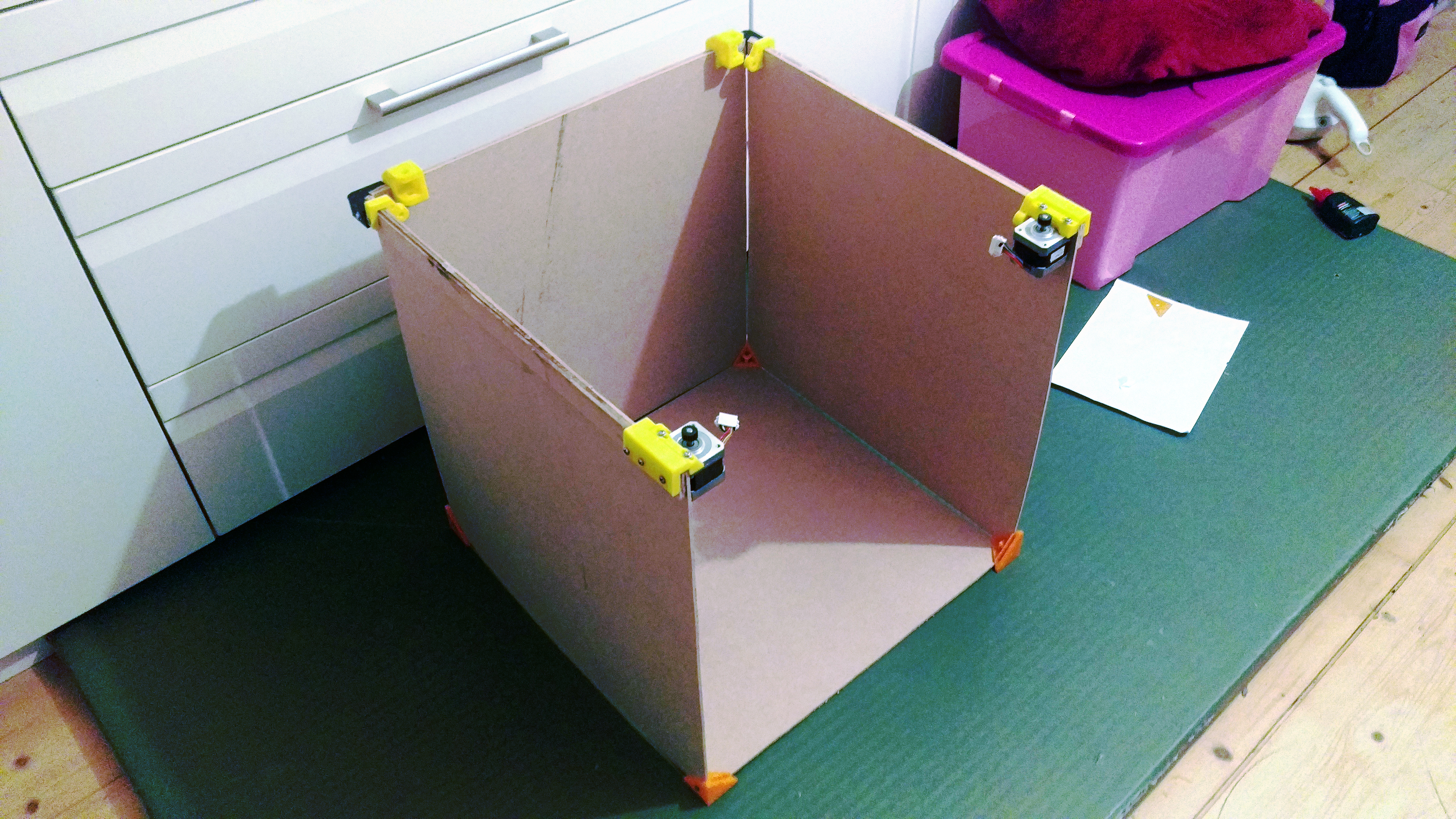
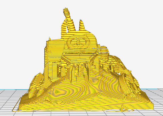
The next issue to solve involves large prints. My first project is to print out a new printer. I’m printing a CoreXY printer. There are STL files available on Thingiverse for this.

I found almost immediately that the default print bed is inadequate.

1. You can’t print directly onto the aluminium, as the plastic will just slip right off. Even if you could, sometimes a print will get stuck and you might have to chip it off, damaging the print bed.
2. The Anet-recommended method is to place painters-tape (a paper tape designed to let people paint without worrying about getting the paint onto glass, etc). This is not good enough, because it involves placing tape precisely so there are no seams, making sure there are no bubbles. It’s annoying work.

The solution I settled on, and others settled on, is to use a glass overlay. I got a cheap picture frame and took the glass from it. It was a little too long in one dimension so it’s currently poking over the edge on one end.

Keeping the glass in place is a problem. The recommended method is to use clips (like from clipboards) to stick the glass to the aluminium, then remove the handles of the clips so they don’t snag on things. I don’t have any yet, so for now, I’ve settled with some teflon tape. It’s designed to not warp in high temperature, so should be fine for a while, until I can print out some proper solutions for this.

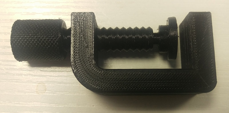
The final problem of the day- I was printing out a piece for the new printer. It initially started very well, printing onto the glass like a dream. However, after the print was about 1cm high, it suddenly came lose from the glass and the printer started printing out a “nest” instead.

After examining the print, I found the problem – the bottom had curled upwards from the bed, reducing the volume that was in contact with it, and making it more likely that the movements of the print bed would break the print free.

The curling is caused by temperature differences between the newly printed layers and already-printed layers. As the plastic cools, it shrinks. If there is even the slightest gap under the plastic when this happens, then this will cause curling.

The solution was to spray hair-spray where the print was to contact the bed. This lays down a thin layer of binding plastic on the glass that increases contact between the print and the bed, reducing the chance that it will come lose.

After printing, removing the print from the glass is a simple matter – I whack the bottom of it with a metal ruler. Instant release, and no damage.